 Constructing the frame for both the 330 and 302 is our next task. We will utilize the end platforms and steps from the otherwise discarded Roundhouse frames. For the center section, a long piece of 0.080" thick piece of Evergreen Styrene is used. Fit the styrene and end steps to the body, but don't glue just yet.
The internal bulkeads are used to support the body on the frame, allowing the styrene frame to slide up into the body approximately 0.1", i.e. hiding the frame except for the underneath view. These bulkheads were fitted from 0.040" styrene, and I used Grandt Line coach door #300-5070 as an insert in the 3 bulkeads I built (2 for the coach, one for the observation. The last bulkead on the observation was a cut down of the rear bulkead provided with the Roundhouse observation kit. Remove from the top to fit, leaving the bottom intact. Once fitted, the bulkeads should be cemented into position.
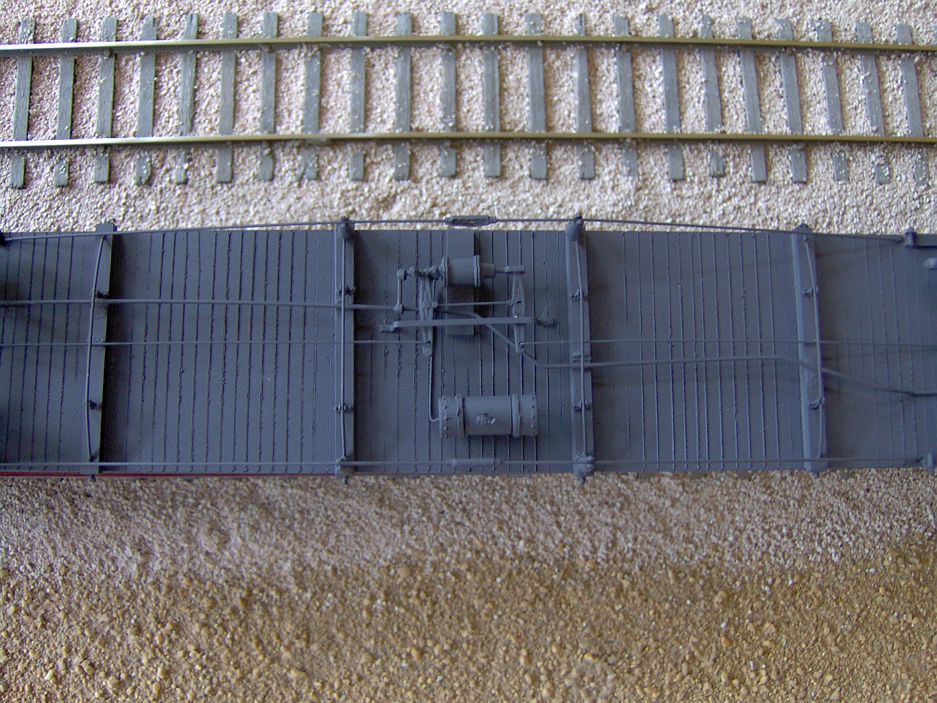
The fit piece of 0.080" styrene for the frame now needs to be scribed cross wise. Refer to the pictures of the black underframe, and lightly scribe lines on 6" centers (or if you don't care about underbody detail skip this step). Once the 330 underframe is scribed, flip it over and scribe one end lengthwise to simulate the rear deck T&G.
Next, use the bolsters supplied with the Roundouse kit, and glue them to the appropriate location on the frame. I would suggest using prototype photos to guide you as much as possible for all these steps. To get the right look and feel of the car, the centerline of the trucks should line up with the appropriate windows etc. Same with bulkheads, needle beams, truss rods and lettering. Thread the bolsters to accept the truck screw once it has dried. The step/platform assembly can now be glued to the center frame and couplers applied. Trucks aren't too easy to come by for this car, but Walthers offers a good stand-in, item 933-1077. Earlier kitbashed models of this car used Central Valley trucks (Model T-25), but the company no longer exists and the trucks are out of production. However, they still sometimes surface on eBay. Here is one search option: Central Valley T-25. As for the couplers, I used wide swing coupler pockets from Kadee.
There are 4 needle beams (4x6" laid flat) running across the bottom. All have their own truss rod, and are meant to support the car crosswise. The two center needle beams also support the queen posts for the main truss rods on the car as well. Use 6" queen posts Grandt Line 300-5050 2 per each needle beam (8 total) spaced per the model photo. For the 2 center needle beams, use 10" queen posts Grandt Line 300-5053 at each end. Note the alignment for the saddle on the queen posts. The ends of the needle beams should be drilled to accept the fishing line we will be using as truss rods. The hole should be centered on the end of the beam and exit the beam 1/8" so the line will wrap over the top of the 6" queen post, across the other queen post, dive back into the beam and exit the other end. Sounds complicated, actually fairly easy to accomplish. Cut a length of line plenty long. Use a soldering iron to melt a blob on one end. Thread the other end through the beam as mentioned. Use tweezers to keep tension on the line just before it dives into the exit point. Melt the protruding end and voila, you have a tensioned truss rod! Install and glue the needle beams.
I would suggest doing the brake system next. The car was built with a PM brake system, however a search of the internet came up empty for HO parts. Instead try a PC brake system, Cal Scale 190-220. Use the model photo as a guide to installation, any questions can sent back to the list. A general note on brake systems: There is a 1.25" brake pipe that runs the length of any car called the "Train Line". At each end are the anglecocks and airhoses, located on the right side of the car as you face it. Somewhere near the location of the brake cylinder, the train line is tapped with a tee, and a 1" branch goes first to a cutoff valve, a dirt collector, and finally the triple valve. In the case of the 330, the triple valve is mounted directly to the brake cylinder, greatly simplifying the plumbing. From the triple, a line is run out to the air resevoir, also known as the auxiliary resevoir. There are other appliances such as retainers, slack adjusters and reducers, but that's the general scheme of the air hookup. Mechanically, the brake cylinder has 2 ends, one dead and one live. The dead end is simply a clevis attach point for one end of a main lever. There are 2 main levers, naturally the other lever attaches to the live end of the brake cylinder, the end which will extend when brakes are applied. The center of the 2 main levers is connected by a very large rod. When the cylinder extends, the other end of the levers travel in the opposite direction, since the middle is fixed by the large connecting rod. Needless to say, this is where the main brake rods are attached leading to the trucks. This overly simplified description skips equalizing levers, hand brakes and several other operating features of the brake system. Truly a marvel, the mechanical design of the system applies equal pressure to every wheel on the car, and will operate in the ustmost adverse weather conditions.
For the main truss rods, we follow much the same procedure as on the needle beams. The rods are actually connected to a large shoe that runs the length of the bolster. The ends of these can be seen near the canted trucks towards the center of the car. I used 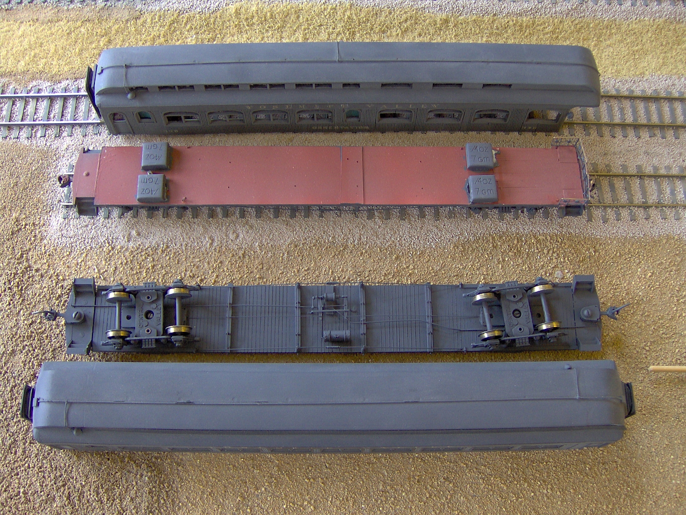 styrene strips, and once attached, drilled the holes for the fishing line where they terminate pointing to the center of the car. The rods are attached to the shoe on a large cast clevis, these are easily approximated by getting a large NutBoltWasher from O-scale and gluing it to the outside. Sure the inside one is missing, but we're not actually connecting anything. Thread the main truss rod and the frame is complete. I added 1 ounce of weight directly over the trucks, and have been very pleased with operation. Sid did bring one of the modified 4-4-0 locmotives, it can handle the 330 and 107 up my worst grade, but couldn't get the 302. Weight will vary depending on trucks, mine are older Central Valley, heavy, but keeps the weight low.
While we have the roofline visible in the photo to the right, the cars were modified in the teens for electricity. The railroad elected to put a large conductor 3 wire electrical connection across the top of the car, protected in conduit. There were stub-outs for the bathrooms, The 330 has one in the middle and front, the 302 one on each end. This leads to choosing an era. For those modeling very early, or contemporary 330 operations, a clean roofline is in order. For those modeling 20's through 40's. a cluttered roof line is the answer.
Post any questions to the YV group, I'll answer any and all. Keep in mind that it is difficult to verbalize every nuance of construction, so refer to the photos to frame your thoughts.
NOTE: You will need to be a member of the group to post messages. Click here to join.